- 4*4 MULTIPLIER VERILOG CODE HOW TO
- 4*4 MULTIPLIER VERILOG CODE FULL
- 4*4 MULTIPLIER VERILOG CODE VERIFICATION
- 4*4 MULTIPLIER VERILOG CODE CODE
- 4*4 MULTIPLIER VERILOG CODE PROFESSIONAL
* all the partial products have been obtained and stored in a array of 8 X 8 matrix. all the partial products have been obtained and stored in a array of 8 X 8 matrix. Integer x) //x is multiplicand AND y is multiplier

Download the files used in this example: Download unsignedmultv.zip.
4*4 MULTIPLIER VERILOG CODE CODE
Synthesis tools detect multipliers in HDL code and infer lpmmult function. This example describes an 8 bit unsigned multiplier design in Verilog HDL. The following is the example of a 4×4 array multiplier.
4*4 MULTIPLIER VERILOG CODE FULL
A full adder has three input lines and two output lines, where we use this as a basic building block of an array multiplier. 4-by-4-array-multiplier Building Blocks of 4×4 Array Multiplier.

Reg p // array which stores the partial products BUILT IN - ARTICLE INTRO SECOND COMPONENT. This video provides you details about how can we design a 4-Bit Multiplier using Dataflow Level Modeling in ModelSim. The 4×4 array multiplier shown has 8 inputs and 8 outputs. Module wallace1(output reg product, input x, y, input clock) multiply operations to be done, it is better to enable a hard multiplier. Additional Comments: 8*8 Wallace Tree multiplier Code for Arduino is based on code from page Using Arduino with an I2C EEPROM.
4*4 MULTIPLIER VERILOG CODE VERIFICATION
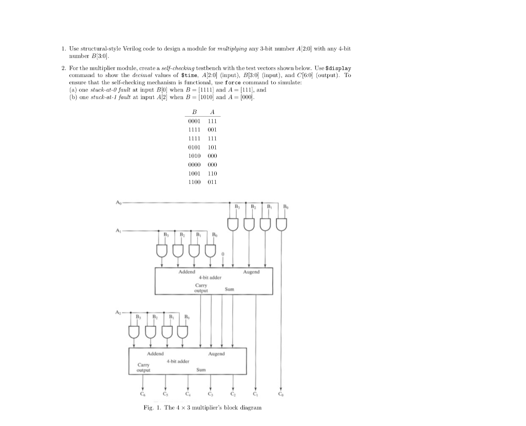
ABC, VIDYALANKAR INSTITUTE OF TECHNOLOGY Design is carried out in Xilinx ISE Design Suite 14.7 using Verilog HDL and verification is carried out in Questa Sim 10.4e using System Verilog HVL environment. Synthesize a circuit from the code and verify its functional correctness.Figure 3.35 A 4 × 4 multiplier circuit. Verilog Code Half Addermodule HA(a,b,sum,carry) Fundamentals of Digital Logic with Verilog Design (3rd Edition) Edit edition Solutions for Chapter 3 Problem 16P: Write a Verilog module to describe the 4 × 4 multiplier shown in Figure 3.35. The final result is obtained from the sum and carry bits of the adders.
4*4 MULTIPLIER VERILOG CODE PROFESSIONAL
Hence, the half adder and the full adder is instantiated for each computation as per the requirement by passing the appropriate parameters. I have more than 13 years of professional experience in RTL design and FPGA. For constructing an 8X8 multiplier, we need 8 half-adders and 48 full-adders i.e. So firstly, a half-adder and a full-adder are designed. Wallace tree multiplier is made up of mainly two components, namely, half-adder and full-adder. The multiplier accepts two 8-bit numbers multiplicand and multiplier and results in 16-bit multiplication. Program 80 B Multiplier Based 2D Convolution Verilog Program 90 C PERL Script for Data Post. Module TP has unconnected port(s) : cout.An 8X8 Wallace tree multiplier is to be designed using Verilog. VERILOG CODING OF 4-BIT BARREL SHIFTER WITH ROTATION module.

Which got me stuck on how i can change the code bcs when i tried to modify myself i got like 11 warnings like"Warning: VCP2597 multiplicator.v : (18, 1): Some unconnected ports remain at instance: stage10. After synthesis of verilog code by using. The tool used for the synthesis of verilog code is genus tool. it is the result obtained the synthesis of verilog code. Module mult(multiplicand, multiplier, product) dada multiplier it requires only 4 partial product addition levels, so there is a area reduction in dadda multiplier and it also consumes less power. First thing is first.
4*4 MULTIPLIER VERILOG CODE HOW TO
In this project,I’m gonna try to explain how to create a 4 bit-multiplier. If it is a combinational logic multiplier it should have been: 4 bit- Multiplier (Verilog) Posted on 24 October 2016 by Muhammed Yaar Kaya. X 3X2X1X0 is the 4 bit multiplicand and Y 3Y2Y1Y0 is the 4 bit multiplier. "module FA(input a,input b,input cin,output s,output cout) Īnd then the guy said "I do not understand why in a 4 bit x 4 bit multiplier you are taking 4 inputs that also of 8 bit, what are they representing. Figure 2: Hardware Architecture of general MAC Array Multiplier A 4 x 4 array multiplier and the functions of M0, M1, M2, and M4 ( M’s are either half adders or full adders) are shown in figure 3. Because when i actually found one which i thought will be good in the comment section a guy said it was wrong and and it has 8bit inputs


 0 kommentar(er)
